With the RevPiNet * classes, we can access the process image via the network. We now use this function to send the value of a GPIO pin of the Raspberry Pi to our process image.
piCtory configuration on the Revolution Pi
On the Revolution Pi, we create a virtual device called virtrpi that the Raspberry Pi uses to exchange data with the Revolution Pi. The first input is called inputbyte1.
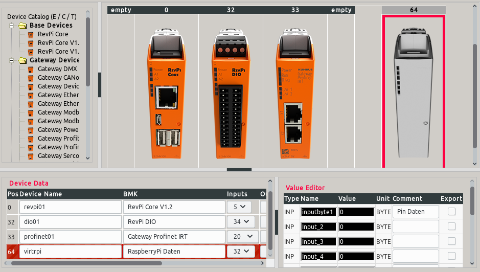
Virtual device virtrpi with position number 64
First INP on virtrpi named inputbyte1.
Via the virtual device, all programs that use the process image can access the data. Whether it is a control program in Python3 with RevPiModIO or logi.CAD, does not matter! Even visualization solutions that use the process image get access to the data.
RevPiPyLoad on the Revolution Pi
So that a system with RevPiNetIO can access the process image via the network, RevPiPyLoad (at least version 0.6.5) must be installed on the Revolution Pi! [Installation Guide]
After installation, the RevPiPyLoad configuration must be adjusted. Of particular importance is a value of the configuration file /etc/revpipyload/revpipyload.conf, which we edit via SSH or directly on the Revolution Pi.
pi@RevPi ~/ $ sudo nano /etc/revpipyload/revpipyload.conf
[DEFAULT]
(...)

[PLCSERVER]
plcserver = 0
(...)
To activate the network access to the process image, the parameter plcserver must be set to 1!
Very important is also the file /etc/revpipyload/aclplcserver.conf, which controls the access to the process image.
Each line of the file has the following syntax: IPADRESS,RIGHT
(several of these permissions are separated by a new line)
IPADDRESS
Single IP address or groups defined with wildcards:
192.168.178.10 -> Only one computer
192.168.178. * -> All computers where the IP 192.168.178. startsRIGHT
0 = read only
1 = read and write
Example:
# PLC-SERVER Access Control List (acl)
# One entry per Line IPADRESS,LEVEL
#
192.168.178.*,0
192.168.178.10,1
All computers in the network 192.168.178.xxx have read access, the computer with IP 192.168.178.10 has read and write access.
After the change, the file must be saved and the service restarted:
pi@RevPi ~/ $ sudo systemctl restart revpipyload
All other parameters are listed HERE.
Prepare Raspberry Pi
First, we need to install the RevPiModIO2 module on the Raspberry Pi. We can do this as described here or via pip3.
pi@raspberrypi:~ $ sudo pip3 install revpimodio2
We can now make the first test on the Raspberry Pi. Be sure, that there is no other control program running on the Revolution Pi, because we use the exclusive mode!
Note: The IP address must of course be changed to your Revolution Pi!!!
pi@raspberrypi:~ $ python3
Python 3.5.3 (default, Jan 19 2017, 14:11:04)
[GCC 6.3.0 20170124] on linux
Type "help", "copyright", "credits" or "license" for more
information.
>>> import revpimodio2
>>> rpi = revpimodio2.RevPiNetIO("192.168.50.36", autorefresh=True)
>>> rpi.core.temperature
49
>>> rpi.io.inputbyte1.value
0
>>> rpi.disconnect()
>>> exit()
If the output looks like this, the test is successful!
Program Raspberry Pi
With the Raspberry Pi we now want to write data into the INPUTS of the virtual device. To make this possible (write to inputs) we use RevPiNetIODriver(...).
# -*- coding: utf-8 -*-
"""This program sends the status of the GPIO pins to the Revolution Pi."""
import revpimodio2
from RPi import GPIO


def cyclefunc(ct):
    """Cycle function which is called by the cycleloop() cyclically."""
    # Write value of GPIO Pin 13 to IO pin13
    rpi.io.pin13.value = GPIO.input(13)


def endfunc():
    """Sets all values of the virtual device to 0 / False at the end of the program."""
    rpi.setdefaultvalues()


# Setup GPIO on RaspberryPi
GPIO.setmode(GPIO.BCM)
GPIO.setup(13, GPIO.IN)

# Setup RevPiModIODriver() for virtual device 'virtrpi'
rpi = revpimodio2.RevPiNetIODriver(
    "192.168.50.36", "virtrpi", autorefresh=True
)

# On the bit 0 of the "inputbyte1" of our virtual device we register an "input"
# with the name "pin13".
# Because we are a driver (RevPiNetIODriver) we can write in inputs!
rpi.io.inputbyte1.replace_io("pin13", "?", bit=0)

# Close the program clean when SIGINT or SIGTERM is sent
rpi.handlesignalend(endfunc)

# In case of a communication error set the virtual device to 0!
rpi.net_setdefaultvalues()

# Start cyclic processing
print("Start cycleloop()")
rpi.cycleloop(cyclefunc)

# After terminating the cycleloop disconnect from the Revolution Pi
rpi.disconnect()

# Cleanup GPIO
GPIO.cleanup()
This program creates an instance of RevPiNetIODriver(...). As parameter, we specify the IP address of the Revolution Pi and the name of the virtual device that our driver instance should use.
Since we want to save the GPIO values as BITs, we can register up to 8 BIT-IOs on our inputbyte1. Via rpi.io.inputbyte1.replace_io("pin13", "?", bit = 0) we register a new BIT-IO with the name pin13, which we can address directly via rpi.io.pin13.
Since we are a driver, we can read/write inputs but read outputs only!
IMPORTANT: With rpi.net_setdefaultvalues() we instruct the Revolution Pi to set all virtual device inputs to default values (normally 0) should the connection be lost! This is very important, as otherwise the set inputs would retain their status in case of a connection failure!
Then we call rpi.cycleloop(cyclefunc) and the RevPiModIO cyclically (standard every 50 milliseconds) executes the function cyclefunc(ct). This function reads out the current status True / False of the GPIO pin 13 and writes the value into our input pin13.
This value is now available on the Revolution Pi!
Optional: Control program on the Revolution Pi
On the Revolution Pi we execute the following program.
# -*- coding: utf-8 -*-
"""Example program to access data of the Raspberry Pi."""
import revpimodio2


def evt_raspberry(ioname, iovalue):
    """Event function for data change of the Raspberry Pi."""
    # Output a line with the current value
    print("Input: {} - Value: {}".format(ioname, iovalue))


# Create RevPiModIO instance
rpi = revpimodio2.RevPiModIO(autorefresh=True)

# On the bit 0 of the "inputbyte1" of our virtual device we register an "input"
# with the name "pin13".
rpi.io.inputbyte1.replace_io("pin13", "?", bit=0)

# We register an event for the new input.
rpi.io.pin13.reg_event(evt_raspberry)

# Close the program clean when SIGINT or SIGTERM is sent
rpi.handlesignalend()

# Start event monitoring and react to events
print("Start mainloop")
rpi.mainloop()
Here we also create a new input pin13 on bit 0 of input inputbyte1.
Afterwards we register with rpi.io.pin13.reg_event(evt_raspberry) an event, which executes the function evt_raspberry(ioname, iovalue) if the value changes. The function then simply writes the IO name and current value in the output.
Start mainloop
Input: pin13 - Value: True
Input: pin13 - Value: False
Input: pin13 - Value: True